Had a frustrating race weekend recently. The event was the TWMX "Slam Fest" at Milestone Raceway here in Socal. An event tailored made for the Alta as it's basically a 5 lap dash for cash. Lots of big time players typically show up and it was loaded this year. Mike and Jeff Alessi, Tyler Bowers (last years winner), Alex Ray, Mitchell Falk, Derek Drake, and all the fast local boys. Of course, I wasn't racing but I let Matt Cerami take a shot with my Alta.
The morning till early afternoon is for practice with the race (two motos) starting around 3:00 PM. It was a very hot (95+) day but we needed to get the bike dialed in for Matt so we arrived early. The first practice session went well as Matt managed about 5 relatively hard laps before the thermal limiting light came on. I was prepared with a huge industrial size fan and plenty of water to keep battery temps in check. Between practice sessions I'd alternate with direct spraying and soaking towels wrapped around the pack. Unfortunately, the light would come on earlier and earlier after each session.
We sacrificed the last couple of sessions just to give the pack more time to cool before qualifying, at least two hours. All the while I'm trying to keep the bike reasonably charged and the pack as cool as possible. It was a full time job!
Qualifying was 30 minutes, fastest lap counted as normal. Matt couldn't even manage one hard lap without limiting. We spent most of qualifying sitting in the infield waiting for the last couple of minutes to make one last attempt. No go. Again, very frustrating.
Now granted, mines a 17 pack. But from that experience I'm sure the MXR pack probably wouldn't have done much better under those conditions. Also, I'm not 100% sure the limiting was due to pack temps as it could have been motor or inverter limiting. I'm not sure there's any way to tell, at least none commonly known. At this point I'm pretty sure it's battery related, however.
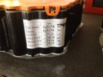
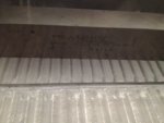
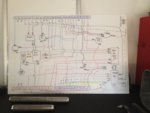
I've been telling myself I got to do something about this situation (pack heat soaking). So this week I finally tore my pack apart to study the design and decide if there's something I can do. Here's some pics and comments.
The Pack was much easier than I was prepared for to disassemble. It only took about an hour including careful deliberations not to break anything or get myself killed (The voltage and amps from this pack CAN kill you, so don't attempt this unless you know how to work with high voltage systems).
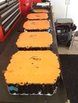
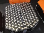
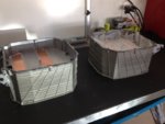
As I suspected, the cell side of the pack is composed of four identical "Modules". The specifics of the cell modules can be found in one of my earlier posts. The housing is a two piece design split horizontally mid pack. Each "half" houses two cell modules. The half's are again compartmentalized with a web or shelf about midway. Each web serves as the main structural interface for the forward module and aft module and as the main thermal path from the modules to the outside air. To improve the thermal conductivity of this relatively thin web, four "heatpipes" (two fwd and two aft) are incorporated into the web. In addition, thermal "paste" is applied quite liberally (too much?) between the module interface surface and the web. The "high power/amp" (+/-) terminations for each module are connected to the next "series" module through insulated "slip pins". The +/- slip pin receptacles on each module have tiny "fingers" which make intimate contact with the uninsulated ends of the slip pin allowing easy installation and good electrical contact (apparently). The modules are connected in series top to bottom, the final negative end needing a more conventional stranded wire routed back up to the top of the back through small hogouts in the webs. Each module is electrically and electronically connected via interconnect harnesses, again routed through small cutouts in the two webs. These allow module to module and module to host communications (via CAN), power and data exchange. There's flashable micro controllers, CAN transceivers, and digital isolators everywhere!
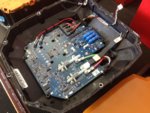
The nadir cover (lid) houses the I/O connector, main power connector (+/-) as well as the main contactor and 5 and 12 volt DCDC converters plus other electronics aboard the cover PCB. The nadir cover has only four connections to the cell modules, main +/-, a separate housing grd and a small 5 pin connector. As mentioned, the cover also connects the cover PCB to the main power connector (to inverter) and I/O connector. The I/O interface supplies the regulated 5 and 12 volts to whatever needs it and is the main CAN interface between the battery pack and the bike.
Initial thoughts? Nothing too surprising so far. I think an externally driven cool plate can be incorporated between the very top and bottom modules and their respective heat sink webs which at a minimum would allow much more rapid heat removal between motos and/or during charging. With the proper design and materials I think this could be done without negatively affecting existing "running condition" thermal control. While it doesn't solve the problem entirely, it will delay the onset after the pack has seen temperature.


