enjoythesilenc
Well-known member
- Likes
- 263
- Location
- virginia
For academic purposes, I dove into the inverter as far as I dared to. I'm an electrical novice so this is part of learning more about how these bikes actually work.
Inverter lives under the seat. The big round structure is a capacitor, I believe. Mine has a H&C label on it, maybe that is a vendor name?![20200501_201926[1].jpg 20200501_201926[1].jpg](https://electricdirtriders.com/data/attachments/5/5403-19fa87fc07dc501059662e467bc2424a.jpg)
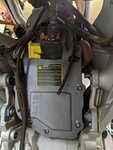
Flipping the bike over on its back reveals the inverter cover, mine is a cool machined one, others might have cast covers.![20200501_195114[1].jpg 20200501_195114[1].jpg](https://electricdirtriders.com/data/attachments/5/5404-e1462edb0d623ecaa0fce88af98319e2.jpg)
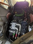
Open the lid to see this![20200513_093034[1].jpg 20200513_093034[1].jpg](https://electricdirtriders.com/data/attachments/5/5405-e4cf2a7dedadd5aba8e7f6b57273f257.jpg)
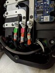
The labels say DC bus on the left, which are the terminals on that big capacitor. Wires from the battery pack (top) and the DCCP (bottom) terminate here. Pop the terminal cover off to see which wires go where
![20200520_092034[1].jpg 20200520_092034[1].jpg](https://electricdirtriders.com/data/attachments/5/5406-9a994f2d52abcd787b8df9db5f1ba59c.jpg)
Next, pull off the busbars on the "AC tray" so we can see what lurks below. I had to destroy part of the plastic cover with a die grinder because of how it was screwed down to the case.
![20200520_105720[1].jpg 20200520_105720[1].jpg](https://electricdirtriders.com/data/attachments/5/5407-af586a890a8e22433ce664fb9132723f.jpg)
I think the brain is that big square chip in the middle. It is mentioned in this post: MXR Negative Contact Relay Failure........ . The connectors along the bottom are ENC encoder and MOT motor temperature? You can see some brown compound smeared on the ring lugs attached to the big terminals, which I think is Penetrox, which is called for on this assembly diagram:
![20200504_084859[1].jpg 20200504_084859[1].jpg](https://electricdirtriders.com/data/attachments/5/5408-c870f786da56489401e83ad2417947ad.jpg)
Removing that pcba gets you down to this level:
![20200520_110702[1].jpg 20200520_110702[1].jpg](https://electricdirtriders.com/data/attachments/5/5409-a785a60daa9c752daad48373bdeb0d7d.jpg)
The black rectangular box is the workhorse. I'm not sure if it generically called the controller or IGBT or powerstage or inverter. Any help here?
Mine is labeled as a Powerex which is a company in PA, USA. Powerex - Complete range of IGBTs and HVIGBTs and other Integrated High Power Semiconductor Solutions
Powerex sold this stuff to Mitsubishi, apparently, so we end up here: MITSUBISHI ELECTRIC Semiconductors & Devices: Product Information | Power Modules [IPMs(Intelligent Power Modules)]
(it's a G1 type intelligent power module) MITSUBISHI ELECTRIC Semiconductors & Devices: IPMs(Intelligent Power Modules) G1 series PM300CG1C065
I see a cover attached with screws so out they must come to get us here:
![20200521_181809[1].jpg 20200521_181809[1].jpg](https://electricdirtriders.com/data/attachments/5/5410-434ad2c02ed79d69e501831acbed8e13.jpg)
The product literature mentions a "six pack" which I think corresponds to these six black rectangles (IGBTs)? I didn't dare go any deeper as there is potting compound below this circuit board.
The last thing I'll show is the little circuit board labeled "current sensor" sitting upon two of the phase busbars:
![20200520_111417[1].jpg 20200520_111417[1].jpg](https://electricdirtriders.com/data/attachments/5/5411-2c9bf3b125b3971c0839deef868d1c79.jpg)
Inverter lives under the seat. The big round structure is a capacitor, I believe. Mine has a H&C label on it, maybe that is a vendor name?
![20200501_201926[1].jpg 20200501_201926[1].jpg](https://electricdirtriders.com/data/attachments/5/5403-19fa87fc07dc501059662e467bc2424a.jpg)
Flipping the bike over on its back reveals the inverter cover, mine is a cool machined one, others might have cast covers.
![20200501_195114[1].jpg 20200501_195114[1].jpg](https://electricdirtriders.com/data/attachments/5/5404-e1462edb0d623ecaa0fce88af98319e2.jpg)
Open the lid to see this
![20200513_093034[1].jpg 20200513_093034[1].jpg](https://electricdirtriders.com/data/attachments/5/5405-e4cf2a7dedadd5aba8e7f6b57273f257.jpg)
The labels say DC bus on the left, which are the terminals on that big capacitor. Wires from the battery pack (top) and the DCCP (bottom) terminate here. Pop the terminal cover off to see which wires go where
![20200520_092034[1].jpg 20200520_092034[1].jpg](https://electricdirtriders.com/data/attachments/5/5406-9a994f2d52abcd787b8df9db5f1ba59c.jpg)
Next, pull off the busbars on the "AC tray" so we can see what lurks below. I had to destroy part of the plastic cover with a die grinder because of how it was screwed down to the case.
![20200520_105720[1].jpg 20200520_105720[1].jpg](https://electricdirtriders.com/data/attachments/5/5407-af586a890a8e22433ce664fb9132723f.jpg)
I think the brain is that big square chip in the middle. It is mentioned in this post: MXR Negative Contact Relay Failure........ . The connectors along the bottom are ENC encoder and MOT motor temperature? You can see some brown compound smeared on the ring lugs attached to the big terminals, which I think is Penetrox, which is called for on this assembly diagram:
![20200504_084859[1].jpg 20200504_084859[1].jpg](https://electricdirtriders.com/data/attachments/5/5408-c870f786da56489401e83ad2417947ad.jpg)
Removing that pcba gets you down to this level:
![20200520_110702[1].jpg 20200520_110702[1].jpg](https://electricdirtriders.com/data/attachments/5/5409-a785a60daa9c752daad48373bdeb0d7d.jpg)
The black rectangular box is the workhorse. I'm not sure if it generically called the controller or IGBT or powerstage or inverter. Any help here?
Mine is labeled as a Powerex which is a company in PA, USA. Powerex - Complete range of IGBTs and HVIGBTs and other Integrated High Power Semiconductor Solutions
Powerex sold this stuff to Mitsubishi, apparently, so we end up here: MITSUBISHI ELECTRIC Semiconductors & Devices: Product Information | Power Modules [IPMs(Intelligent Power Modules)]
(it's a G1 type intelligent power module) MITSUBISHI ELECTRIC Semiconductors & Devices: IPMs(Intelligent Power Modules) G1 series PM300CG1C065
I see a cover attached with screws so out they must come to get us here:
![20200521_181809[1].jpg 20200521_181809[1].jpg](https://electricdirtriders.com/data/attachments/5/5410-434ad2c02ed79d69e501831acbed8e13.jpg)
The product literature mentions a "six pack" which I think corresponds to these six black rectangles (IGBTs)? I didn't dare go any deeper as there is potting compound below this circuit board.
The last thing I'll show is the little circuit board labeled "current sensor" sitting upon two of the phase busbars:
![20200520_111417[1].jpg 20200520_111417[1].jpg](https://electricdirtriders.com/data/attachments/5/5411-2c9bf3b125b3971c0839deef868d1c79.jpg)


