Home built linkage guard skid plate

Border Dave

Active member
Likes
31
Location
Bellingham, Washington
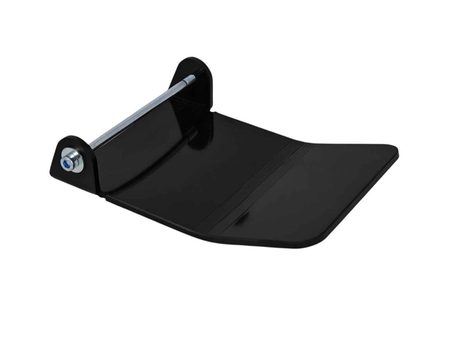
I got tired of waiting for someone to sell a linkage guard/skid plate, so I made my own from a very thin (3.5mm-4mm) high density polyethylene (HDPE) cutting board.

Fy8vAz.jpg

Fy8LVT.jpg

Fy8Mnb.jpg

Fy8uEr.jpg

Fy8DOF.jpg

Fy8FsD.jpg


EDIT: Now that I've had time to think about this I can see the flaw with this design, i.e. the bolts are going to get ripped off by a big rock. I'm going to see if there's a way to mount the guard under the factory skidplate instead.
 
Remember that Stark has stated that using an aftermarket skid plate would void the warranty; I don't know about a modification like this one.
You could try countersunk screws to avoid having protruding heads.
 
Here are a few more photos test fitting the skid plate above the factory skid plate:

Fafokv.jpg

FafMa2.jpg

Fafv9o.jpg

I still need to buy two shorter bolts and a flexible socket extension so that I can tighten them. I should be able to finish up with this on Sunday.

The way it's now mounted it doesn't even touch the factory skid plate. The bolts that attach the new linkage guard are screwed into the top of the threaded bosses that are used to hold the factory skid plate on. I'll take final pics on Sunday.
 
Here are a few more photos test fitting the skid plate above the factory skid plate:

View attachment 15932

View attachment 15933

View attachment 15934

I still need to buy two shorter bolts and a flexible socket extension so that I can tighten them. I should be able to finish up with this on Sunday.

The way it's now mounted it doesn't even touch the factory skid plate. The bolts that attach the new linkage guard are screwed into the top of the threaded bosses that are used to hold the factory skid plate on. I'll take final pics on Sunday.
Great idea for mounting, but how much thread engagement are you getting?
Ideally you should have a length of 1.5*the thread diameter, but could probably get away with one diameter of length.
 
In the first pic you can see there are about five full turns left. The factory skid plate bolt takes up about the same amount.

EDIT: I just went back and checked. With the longer bolts there are only about 3 1/2 full turns until it bottoms out. At 1.25 threads per mm, that equals 4.375 mm of thread engagement. I wonder if that would be enough if I used blue thread locker? I'll try it and find out...
 
There were many aftermarkets that were good. More protective, more cooling, and with good design protecting linkage and battery. Stark would not support warranty if used. My AVS plate was recalled and they did refunds. Stark stated that the shear of the mount bolts was the issue. This could have been easily addressed by the 3rd parties like AVS but there was probably other legal stuff and they chose a complete refund. Your design may avoid Stark's initial mount concern.(y)
 
There were many aftermarkets that were good. More protective, more cooling, and with good design protecting linkage and battery. Stark would not support warranty if used. My AVS plate was recalled and they did refunds. Stark stated that the shear of the mount bolts was the issue. This could have been easily addressed by the 3rd parties like AVS but there was probably other legal stuff and they chose a complete refund. Your design may avoid Stark's initial mount concern.(y)
I agree, this add-on linkage protector will not have any effect on warranty, and is undetectable if removed.
 
KTM sells an extension to their skidplate which can be rather easily modified to fit on the Varg. It has an "hook" that can be hooked into the crossbeam on the Varg frame and then is just clamped be the stock skidplate. You have to remove some material from the skidplate foam to make space and create a groove (I used a heated steel bar) on the extension to fully fit onto the crossbeam - just be a little creative. The massive hook will make it stay in place even with severe hits. Has been working great for me for many hours of semi-hard enduro ;)

KTM LINKAGE PROTECTION - A4600309002

0261681_0.webp

Michael
 
In the first pic you can see there are about five full turns left. The factory skid plate bolt takes up about the same amount.

EDIT: I just went back and checked. With the longer bolts there are only about 3 1/2 full turns until it bottoms out. At 1.25 threads per mm, that equals 4.375 mm of thread engagement. I wonder if that would be enough if I used blue thread locker? I'll try it and find out...

Some considerations:
• One of the problems of a short thread engagement is the possibility of loosening and IMO the thread locker would solve that.
• Bottoming the screw out against the OEM screw underneath will affect its clamping force and I think it should be avoided.
• Generally, the idea of 1.5 times the diameter for steel-to-steel fastening is that usually the coil closest to the head of the screw will take 1/3rd of the torque, the second something less and so on until the 7th coil doesn't take any considerable torque at all. I think that all this, though, is based on the idea that once the fastener is tightened it won't be subject to any radial load even when the objects fastened together are loaded in that direction, because the friction between the surfaces, generated by the axial action of the threads, will keep everything in place. So the thread works only in the axial direction.
In your case, this area indicated by a green circle
mating surface.jpg
is not designed to mate to other components and the same goes for the cutting board. Therefore, when clamped, the surfaces may slide under radial load and load the screws radially, bending or braking or stripping something.
That's why I'd choose low resistance screws that can act as sacrifical parts. Just make a slot on their face opposite to the head so that in case they snap you can remove them from below with a screwdriver.
 
Some considerations:
• One of the problems of a short thread engagement is the possibility of loosening and IMO the thread locker would solve that.
• Bottoming the screw out against the OEM screw underneath will affect its clamping force and I think it should be avoided.
• Generally, the idea of 1.5 times the diameter for steel-to-steel fastening is that usually the coil closest to the head of the screw will take 1/3rd of the torque, the second something less and so on until the 7th coil doesn't take any considerable torque at all. I think that all this, though, is based on the idea that once the fastener is tightened it won't be subject to any radial load even when the objects fastened together are loaded in that direction, because the friction between the surfaces, generated by the axial action of the threads, will keep everything in place. So the thread works only in the axial direction.
In your case, this area indicated by a green circle
View attachment 15944
is not designed to mate to other components and the same goes for the cutting board. Therefore, when clamped, the surfaces may slide under radial load and load the screws radially, bending or braking or stripping something.
That's why I'd choose low resistance screws that can act as sacrifical parts. Just make a slot on their face opposite to the head so that in case they snap you can remove them from below with a screwdriver.
You sound like a very knowledgeable and talented engineer. Thank you for posting your well thought-out response. I would never have thought to make a slot on the bottom of the screw in order to get it out if it breaks. That's just brilliant! I'm not sure what you're referring to when you say "low resistance screws." Can you provide a web link for an M8 low resistance screw?

EDIT: Are aluminum, brass, or plastic what you are calling "low resistance?"
 
Back
Top