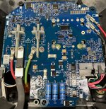
A pack DC-DC section dead after left charging.


JP racing

Well-known member
Likes
56
Location
New York, NY
Does anyone know of anyone who has had success working on the low voltage DC section of the battery packs? My low voltage section is dead and I have neither the parts or equipment to do a rework of the board.

My other alternative is to try to rig up an alternative 12v power source which I would like to hear if anyone has done that!

Thanks all, struggling to get going for race season, my season opens Sunday.
 

Mark911

Well-known member
Likes
1,123
Location
Corona Ca
What model? The R packs are much easier to repair compared to the A pack. I've done both and usually I don't charge anything other than for parts (the DC-DC downconverter can run anywhere from $150 to $550 depending on how you want to go) if that's the only issue.
 

JP racing

Well-known member
Likes
56
Location
New York, NY
What model? The R packs are much easier to repair compared to the A pack. I've done both and usually I don't charge anything other than for parts (the DC-DC downconverter can run anywhere from $150 to $550 depending on how you want to go) if that's the only issue.
It’s an A pack. When powered with outside 12v source everything appears perfect. I toyed with the idea of adding a 12v rechargeable battery.

At this point the cover is off the pack. They soldered the stupid heat sink through the board on the A pack. It’s actually a pretty good design, should be very shock resistant, but a PITA to rework.

If I had the part in hand I could probably find a rework house locally but I can’t even get the board off the cover now.

External 12v source is looking better and better.
 
  • Like
Reactions: #76

JP racing

Well-known member
Likes
56
Location
New York, NY
3F5A1C1F-46F1-40C0-8DB2-4BCAD8F218B2.jpegHere’s the pics
Looking at it now it doesn’t look so intimidating.

The four screws attach the heat sink to the cover and the four solder joints HV-/+ OUT-/+ attach the converter to the board
Probably those 3 top and 2 bottom pins too.

Unfortunately heat sink is attached to converter.
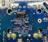
4B5292A5-2D9F-49AA-B91A-6EA3F9E27EEF.jpeg
 
  • Like
Reactions: #76

Mark911

Well-known member
Likes
1,123
Location
Corona Ca
keeping all 8 solder joints fluid while you gently pry up the board is a tricky process. I've done it a dozen or more times so it can be done with the proper process. Remember to unscrew the contactors as they'll prevent the board from popping off.
 

JP racing

Well-known member
Likes
56
Location
New York, NY
I have been holding off as it looks like it's also potted, that makes it sound like heating all the solder joints simultaneously may be enough to get it out.

Thanks for the suggestions!
 

rayivers

Well-known member
Likes
558
Location
CT, USA
Solder Wick or similar could be a great help - you might end up with several loose joints & only a few left to simultaneously heat. I also try to 'pre-load' the PCB/component w/thin plastic or wood wedges pushing up on it, so both hands are free & it instantly tries to move when the solder melts. Another technique for multi-lead components I wish I'd used more often over the years is to CAREFULLY snip the leads and remove the IC or whatever, then unsolder & remove the lead sections one by one. I've also had to resolder components that turned out to be OK and difficult to find though, so there's that. :) Surely you know all this already, just throwing it out there to maybe help others.
 

JP racing

Well-known member
Likes
56
Location
New York, NY
Reworking boards has never really been my thing and I really appreciate your advice.

I think you all have convinced to step back to component testing everything I can see that might connect first before I try taking the board off.
 

rayivers

Well-known member
Likes
558
Location
CT, USA
I just took another look, and wondered if you'd tried loosening (not removing yet) the four Torx screws visible thru the PCB holes, and after that the eight nuts to the left? A lot to hope for, but it would be so cool if the whole PCB + unseen bottom components loosened up on whatever they're mounted to below, and lifted up intact w/fasteners removed.

NOTE: EXTREME CAUTION advised on everything mentioned above, as it looks like most or all these fasteners connect to MEGA HVDC power. I'd heat-shrink all the tools I planned to use 1st, wear gloves, be terrified of every pointy or sharp edge, tape/plastic-shield stuff, etc. etc.
 

JP racing

Well-known member
Likes
56
Location
New York, NY
I just took another look, and wondered if you'd tried loosening (not removing yet) the four Torx screws visible thru the PCB holes, and after that the eight nuts to the left? A lot to hope for, but it would be so cool if the whole PCB + unseen bottom components loosened up on whatever they're mounted to below, and lifted up intact w/fasteners removed.

NOTE: EXTREME CAUTION advised on everything mentioned above, as it looks like most or all these fasteners connect to MEGA HVDC power. I'd heat-shrink all the tools I planned to use 1st, wear gloves, be terrified of every pointy or sharp edge, tape/plastic-shield stuff, etc. etc.
I did do that. It seems very firmly connected still, maybe by more than just solder, think there may be some potting involved.

Agreed, these battery packs can be quite dangerous when charged ( mine is probably at 90%), fortunately this design makes it hard to zap yourself. Taking off the top cover disconnects the HV+ busbar and then you can just disconnect the negative lead and separate the top cover from the battery modules. Once the top cover is off I don't think it's connected to the batteries except by the negative lead.
 

rayivers

Well-known member
Likes
558
Location
CT, USA
OK, bummer but worth checking out. Tyler Monagan had an A-pack partial teardown video on Youtube which you've surely watched already, too bad he never did part 2.
 

Mark911

Well-known member
Likes
1,123
Location
Corona Ca
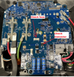
You can look up the data sheet from the part number on that chip and test. Simply apply a couple volts to the switch lead and see if there's continuity between the other two leads. The fuse is obvious. Remember, you'll need to use a bit of solvent to remove the conformal coating first. Not too much, just a bit on a small paint brush.


1683222553997.png
 

Oded

Well-known member
Likes
869
Location
Israel
I did do that. It seems very firmly connected still, maybe by more than just solder, think there may be some potting involved.

Agreed, these battery packs can be quite dangerous when charged ( mine is probably at 90%), fortunately this design makes it hard to zap yourself. Taking off the top cover disconnects the HV+ busbar and then you can just disconnect the negative lead and separate the top cover from the battery modules. Once the top cover is off I don't think it's connected to the batteries except by the negative lead.
Just out of curiosity, did you repair the BCU?
 
Top Bottom