Dirt-E
Well-known member
- Likes
- 61
- Location
- King George, VA
In advance, this is a long post (my apologies!) But I wanted to be thorough.
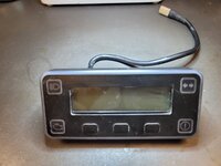
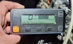
After reading through some other posts on the topic of repairing Alta display screens, I got all the stuff to perform the fix on mine, and was pretty successful.
Huge thanks to the direction of Philmore!
But because his post was like 6 pages in, I wanted to point out what I did and what it took to replace my LCD. Sorry I couldn't make it a video, but hopefully the pictures are descriptive enough.
While the full replacement of the LCD and backlight wasn't terribly difficult to do, it was a bit nerve-wracking because I wasn't sure if it would work. Happily, it came out okay, and it looks like I've got my favorite bike back! (Although I'm not sure if the backlight is actually working yet).
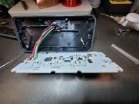
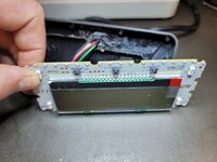
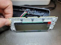
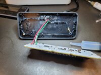
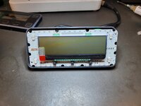
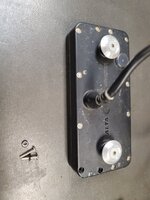
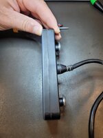
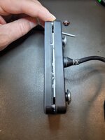
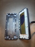
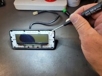
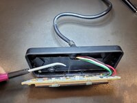
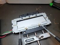
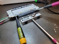
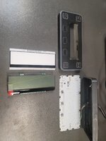
The whole display opens up pretty easy as long as you don't go prying too hard on it after removing the screws. There is some yellow-ish glue they used to stick the board to the backshell, but it comes out with gentle persuasion. I removed as much glue as possible from the board and backshell because I was going to use a better adhesive to close it up.
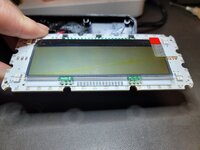
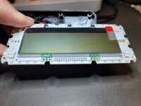
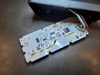
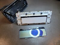
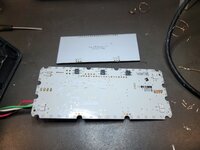
Once I got the main board out of the shell, I had to figure out how to remove the LCD. I didn't quite understand how it was assembled at first, but eventually figured out that it was layered together and soldered into one unit.
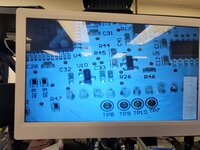
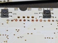
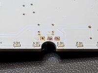
The hardest part of the whole process was getting the headers removed from the main board (the backlight PCB is sandwiched between the main board and the glass polarizer, which has the pins attached to it).
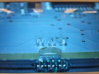
The backlight also had some kind of glue or sticky substance underneath it, so it didn't come up very easily (the glass got completely destroyed during removal). The polarizer pins go through both layers, so my solder remover couldn't get it all out in one go. It wouldn't come off the main board without prying, and I was really worried about breaking the board in half. But, they're pretty darn tough. Eventually, I just cut the pins and then solder-braided the rest of the joints out (I also used some precision cutters to gently pull on the pins to release them from the PTHs). After that, it was a quick cleanup and then wait for the glass to show up (I didn't realize I needed to order two parts so had to wait for the second part for a few days).
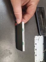
Reassembling the LCD parts involved removing the protective films, inserting the pins through both PCBs, and then soldering each of them until they were all filleted. I couldn't get all of them to flow through both vias (those might have been ground planes). Unfortunately I had to hit it with solder on both sides (which is a no-no in soldering), but it worked. I might have to work on that technique another time.
I used some clear Dowsil 3145 adhesive, in thin beads, on the back cover to replace the amber colored stuff that was in there originally. I did not replace the tacky black glue around the cable, because I know that's what they used for the battery module seals and it works great.
Lastly, I would recommend getting new o-rings for the back screws because they were either deformed or lost some material when I opened mine, but I figure I can replace those another time. Just keep the water spray off the screen anyway.
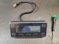
I hope this helps. Let me know if you have any questions.


