The R pack wirebond issue


snydes

Moderator
Staff member
Likes
2,797
Location
Pennsylvania
So by now most of us regular forum rats have heard of the dreaded "code 36" issue. Code 36 indicates a voltage imbalance which could happen for a whole host of reasons. When we are talking about the 2018 R packs the culprit will likely be a disconnected cell due to some issues they had in manufacturing with the wirebonding process. The "wirebond" refers to the small aluminum wire that connects both the positive and negative points on the cell to the module PCB. This wire will act as a fuse in the event of a cell failure that could potentially save the entire pack from further damage. Unfortunately we were told very little about this problem, and that is no fault of our ex Alta friends here as they likely were prohibited to talk about it. Fortunately most of our members here that had experienced the fault were able to get their packs replaced before the shutdown. Unfortunately @Bloak and myself were not so lucky. After much frustration trying to understand what was going on inside my pack and with very little info being disclosed, I decided to see for myself what exactly was the issue. Opening up the pack is not to be taken lightly and is VERY dangerous, you should be trained in electrical safety and have the appropriate equipment to do it. If you are at all unsure DON'T DO IT! We are talking about voltages that will kill you and a battery that could turn into a firebomb. Now that we got that out of the way let me show you what the actual problem looks like;A4706A1B-82E4-4564-8B2F-05474A8432EA.jpeg
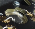
Take note to the upper most fuse on the negative connection of the cell. That is the bad connection, that's all it takes to cause this problem. I would take an wild guess that most if not all the wirebond problems were on that negative connection. Why did they all of a sudden have problems with R packs and not A packs? I think if we look at a comparison of the Panasonics used in the A packs to the Sonys used in the R packs we could make another assumption;50224E04-8F18-430C-8ED6-E6099FF58F07.jpeg
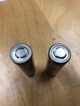
Sonys on left, Panasonics on right (picture courtesy of AltaWest). Note the somewhat wider, flatter lip where the negative connection is made on the Panasonics. We could conclude that this smaller target was just enough to cause a nightmare with the setup of their wirebonding machine.

What can be done to repair this? At this point there is no practical repair that we know of that would not somewhat negate the engineered safety that the OEM fuse wire provided. This is essentially one of the biggest problems with "rebuilding" packs, how to recreate the fuse wire that was engineered for the pack. I think in time there will be, but for now it's still a work in progress.

This is my take on the situation, and I may be wrong about some of the conclusions I have drawn. This post is meant to educate our members so they know what the heck we are referring to when we are taking about wirebonds and fuse wire, etc.

Feel free to discuss.
 

snydes

Moderator
Staff member
Likes
2,797
Location
Pennsylvania
I think one fuse-wire per battery should be sufficient, shouldn't it?

That's a question I'd like to know as well. Somewhere I read or listened to discussion where they were talking about cell level fusing and the possibility of an internal cell malfunction that would cause it to go reverse polarity. I have no idea if that's actually a thing or not. It could be that the double fusing was just the easiest way to make both connections due to the unique single end connection design.
 

snydes

Moderator
Staff member
Likes
2,797
Location
Pennsylvania
Now thanks to the access to the Multi-Tool software we can see what this code 36 imbalance looks like on the battery graph;
60.JPG
Now note we have 4 modules, each a different color, made up of 21 individual bars. Each "bar" represents a parallel group of six 18650 cells. Now I can confirm after locating my bad connection that the numbering of the modules goes from the bottom up, so module 0 is the module at the very bottom of the battery. Note how module 2, P group 10 is much lower, that's obviously my problem group with the bad connection. This picture was taken at about 60ish percent SOC if I recall correctly.


100.JPG
Here is my bike now at 100% SOC. A couple things here worth noting. First, take note at the voltages. Pretty much all at the 4.08v area. We know that the max charge on an 18650 is 4.25, we also know that it's not a good idea to charge all the way to 4.25v, so Alta has programmed in a comfortable margin to keep from stressing those cells from charging to max capacity. Next, note my problem group, now it's higher than everything else.... why is that? All I can deduct is since the capacity of that group is less than everything else, now it takes less time to charge those five cells to the same voltage as the rest, so now that group is the first to be depleted and the first to be recharged. What this all means for a bad wirebond pack on the discharged end is where we really have problems.
 

snydes

Moderator
Staff member
Likes
2,797
Location
Pennsylvania
Not enough room for the negative connection to get two electrodes in there. It’s way tighter in that spot than the pictures would lead you to believe. Also, any spot weld method would necessitate the use of a different material than was engineered for the OEM fuse wire. Would it be the best alternative at this point? Very likely so.
 

gewoontim

Well-known member
Likes
55
Location
The Netherlands
I would guess spot welding to the top is really difficult, if not dangerous because of the change hitting the plus of the cell. If you can eject the cell, maybe you can spot weld a tin lip on the side of the cell? Then you can solder the fuse to this lip, which is probably easier. This only works if the cell is not extremely tight in the cell holder.

Edit: now that I'm thinking about it. It might even work with soldering. If you use a really small tip and heat up the wire a lot, you might pull it off by just using a really small amount of solder. Maybe you can even protect the positive end by a 3d printed cover or something.
 

Redwolf

My dog thinks I'm cool
Likes
1,677
Location
Brinnon, Wa.
I would guess spot welding to the top is really difficult, if not dangerous because of the change hitting the plus of the cell. If you can eject the cell, maybe you can spot weld a tin lip on the side of the cell? Then you can solder the fuse to this lip, which is probably easier. This only works if the cell is not extremely tight in the cell holder.

Edit: now that I'm thinking about it. It might even work with soldering. If you use a really small tip and heat up the wire a lot, you might pull it off by just using a really small amount of solder. Maybe you can even protect the positive end by a 3d printed cover or something.
The cells are epoxied into the cell holder, nobody has attempted to remove a single cell from the pack yet. It is currently assumed that to remove a cell will require destructive techniques.
 

Mark911

Well-known member
Likes
1,123
Location
Corona Ca
The cells are epoxied into the cell holder, nobody has attempted to remove a single cell from the pack yet. It is currently assumed that to remove a cell will require destructive techniques.

We're all assuming the cells are epoxied to the cell support, we don't know for sure. What we DO know is that the cell support is composed of two halves, upper and lower parted down the middle like a couple of pancakes. The top surface of the upper support has a bunch of tiny screw threads for securing the PCB and the bottom surface of the lower support has the relatively thin heat sink/spreader bonded to it. The only thing holding the upper support to the lower support is the 9 long screws that essentially sandwich it all together while also securing the entire module to the main housing. The 9 screws use long metal "sleeves" to limit/set the amount of compressive pressure seen between the heatsink and housing and therefore the ultimate structural strength and thermal conductivity (working through a paste thermal interface material).

Now, all 126 18650 cells in each module are "trapped" between the PCB and the Heatsink. IT MAKES SENSE to assume that the same bond use between the heatsink and the lower cell support ALSO bonds the negative side of each cell to the heatsink for structural and thermal reasons (actually, that's probably the primary purpose and the heatsink to support bond is secondary). Beyond that the only obvious mechanical connection between the cells and the module are all the wire fuses.

From a cell removal/replacement perspective it would be advantageous if the bond between the negative cell and the heatsink was the ONLY bonding done in the module. This would make things pretty easy to extract individual cells. However, until someone actually attempts a cell removal we won't know for sure.

Some members on the forum have gotten access to the raw parts that make up the module, including the two support halves. Some detailed/closeup pictures of an individual cell enclosure could help us gain insight without risk.
 

autohog

Member
Likes
17
Location
Ca
If you guys haven’t watched electrobrapps video then you should. In the last half of the video he shows you all of the parts he scavenged on the dreaded last day including what looks to be each of the individual parts of a battery as well as more than one complete spare battery(s).
 

Rix

Self proclaimed macho man extraordinaire
Likes
449
Location
Fallon NV
Just curious, has there been any reported problems with 2019 EXR battery issues with VIN#s after say 140?
 

Redwolf

My dog thinks I'm cool
Likes
1,677
Location
Brinnon, Wa.
Just curious, has there been any reported problems with 2019 EXR battery issues with VIN#s after say 140?
From what I understand, the problem was solved before the EXR began production.

And if it makes you feel any better, my EXR #103 has been problem free for 1200 miles with 70 hrs on the clock now.
 

Rix

Self proclaimed macho man extraordinaire
Likes
449
Location
Fallon NV
From what I understand, the problem was solved before the EXR began production.

And if it makes you feel any better, my EXR #103 has been problem free for 1200 miles with 70 hrs on the clock now.
That is good to know. And it does make me feel better.
 

revoltlution

Keep yer cool, don't get hurt, and never give up!
Likes
394
Location
St Johns, Portland, OR 97203
I've got EXR #151 and I've had only two troubles:
- had a nasty throttle fault (fixed by a firmware update)
- refuses to charge sometimes (110V error). I think my charger's GFCI is flakey.

Otherwise
 
  • Like
Reactions: Rix

Mikec265

Well-known member
Likes
270
Location
16412
I've got EXR #151 and I've had only two troubles:
- had a nasty throttle fault (fixed by a firmware update)
- refuses to charge sometimes (110V error). I think my charger's GFCI is flakey.

Otherwise
I have the same charge problem on 110 with a fast charger with my MXR. After a few tries it finally goes.
 

VINSANITY

Well-known member
Likes
398
Location
Texas
I've got EXR #151 and I've had only two troubles:
- had a nasty throttle fault (fixed by a firmware update)
- refuses to charge sometimes (110V error). I think my charger's GFCI is flakey.

Otherwise
I have EXR 155 - was your throttle fault related to the warrantee recall - my dealer did the software update before shipping and so far no problems with 200 miles.

Also was your Charger the 240 volt fast charger working with a 120 volt adapter or was is a 120 volt charger.
 

revoltlution

Keep yer cool, don't get hurt, and never give up!
Likes
394
Location
St Johns, Portland, OR 97203
@VINSANITY yes throttle fault was part of the recall. I feel I was one of first to bring it to Alta attention. Just got my bike and popped my first wheelie, came down a bit hard (reverse on the throttle) and the bike was hard failed until a key cycle. Essentially unrideable! That was a bummer first-three-weeks.
Also yes, I have the fast charger with a 120 adapter.
 

Similar threads

Top Bottom