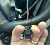
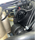
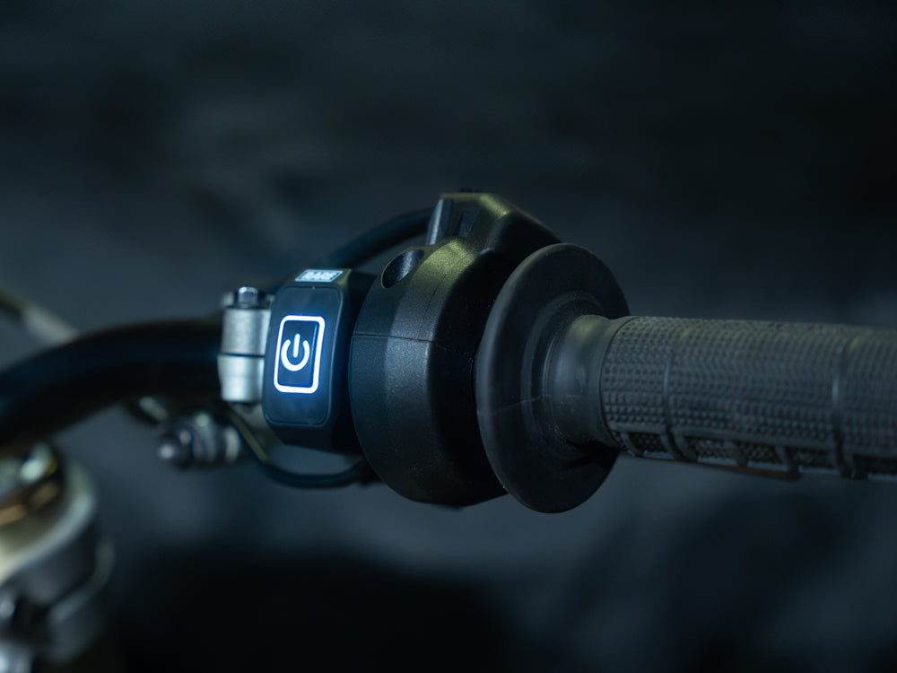
First off, I have no direct experience with Higo connectors/cabling and am looking for advice from the collective here on sourcing and/or self-fabricating (if even possible as they are over-molded) cable assembles.
That said, this is what I am conceptualizing:
In looking for a solution for my EX toward powering a GPS, I am looking for a power tap means to run my GPS, 12Vdc, a few milliamps at most. I have researched a bit and understand the headlight is 12Vdc powered. I have also ID’ed the 5 pin Higo connectors (M & F), I think, that Stark has selected to connect the headlight/turn signal cable to the bike’s charging module.
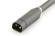
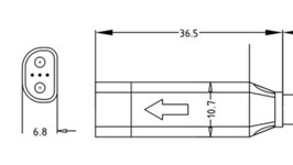
Z511BG P Male https://www.higoconnector.com/en/e-bike-connector/z511bgp00ft1000
Z511BM P Female https://higoconnector.digitaledoeners.be/en/e-bike-connector/z511bmp00ft1000
Listed under their E-Bike connector series.
I realize the links are for a cable assy, but the connector referenced is key for me.
I am envisioning a splitter type patch cable perhaps 200 to 300mm in overall length that one leg will connect between the headlight/turn signal connector (use all 5 circuits) and its mating receptacle on the backside of the bike’s charging module. The second leg would split off and use as a 12Vdc aux power source. That source would be one of the larger pins, I suspect, that carry the headlight current. The Higo connector specs state the 2 larger pins are rated to 20 amps, the 3 smaller pins are 2 amp rated. I would only use the 2 large pins as I suspect 1 is a common ground and other headlight positive. The other 3 used for turn signals, and high beam control signal. I’d need to do some ohmmeter pin out research to confirm, but as the cabling is all sealed, having a break-out harness to test things would be beneficial.
Does anyone have comments or suggestions as to how I could proceed?
I do have an email into Higo directly asking this exact scenario. Am awaiting response which I will share here if they reply.
Thanks.
EDIT later in day: I found an alternate way to access aux power from Stark EX. I'm no longer pursuing Higo splitter.
That said, this is what I am conceptualizing:
In looking for a solution for my EX toward powering a GPS, I am looking for a power tap means to run my GPS, 12Vdc, a few milliamps at most. I have researched a bit and understand the headlight is 12Vdc powered. I have also ID’ed the 5 pin Higo connectors (M & F), I think, that Stark has selected to connect the headlight/turn signal cable to the bike’s charging module.


Z511BG P Male https://www.higoconnector.com/en/e-bike-connector/z511bgp00ft1000
Z511BM P Female https://higoconnector.digitaledoeners.be/en/e-bike-connector/z511bmp00ft1000
Listed under their E-Bike connector series.
I realize the links are for a cable assy, but the connector referenced is key for me.
I am envisioning a splitter type patch cable perhaps 200 to 300mm in overall length that one leg will connect between the headlight/turn signal connector (use all 5 circuits) and its mating receptacle on the backside of the bike’s charging module. The second leg would split off and use as a 12Vdc aux power source. That source would be one of the larger pins, I suspect, that carry the headlight current. The Higo connector specs state the 2 larger pins are rated to 20 amps, the 3 smaller pins are 2 amp rated. I would only use the 2 large pins as I suspect 1 is a common ground and other headlight positive. The other 3 used for turn signals, and high beam control signal. I’d need to do some ohmmeter pin out research to confirm, but as the cabling is all sealed, having a break-out harness to test things would be beneficial.
Does anyone have comments or suggestions as to how I could proceed?
I do have an email into Higo directly asking this exact scenario. Am awaiting response which I will share here if they reply.
Thanks.
EDIT later in day: I found an alternate way to access aux power from Stark EX. I'm no longer pursuing Higo splitter.

