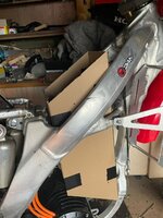
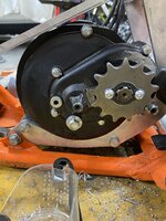
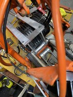
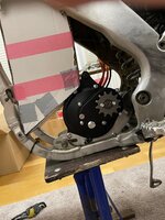
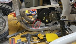
Yet another CRF 250 Build but its my first so... ;)


unluckypanda

New member
Likes
0
Location
California
About to buy a 20s13p battery from Amorge myself with a similar shape. Going with their Lishens instead of the Samsung 50S. P42A/P45B is way too out of budget for me.

I thought about going 50S because at 13p I'd get 65AH with a peak of about 335a. I would use 300a continuous at most. Then I thought it might not last even though theres 13 extra AH, due to heat from using the cells near their peak often while riding. Would cost me around ~$1450 for the 50S cells, ~$1900 for P42A, but ~$1000 for Lishens.

Going to pay tomorrow morning
 

fmxxx666

Active member
Likes
40
Location
Hamburg Germany
@unluckypanda
I was at the same point as you now.
I took the time to watch this Video and try to learn everything about the cells along the way (thats a freaking 4H+ Video xD)
but the guy put a lot of effort into this:

but after watching this I sattled on the Molicel P45B as it gives me the most bang for the bug for my build as of right now.
 

fmxxx666

Active member
Likes
40
Location
Hamburg Germany
Today is the day I just placed my Order at Amorge :)


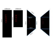
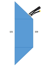
so my final Battery Shape for the Honda CRF 250 2009 (same frame from 2006-2009) is:

Molicel P45B
22S13P 81.4V 58.5AH (Optional 20S14P 72V 63AH but I went with 22S)
Metal Casing
Open Discharge (BMS only for Charging)
QS10 Plug for Discharge
XT90 Plug for Charging
QS10 Plug Battery Leads 650mm Length
10A Charger
Shipping by air
batterysize_final1.png


plugs_position.png


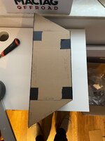
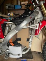
Unbenannt.jpgUnbenannt1.jpgUnbenannt2.jpgUnbenannt3.jpg

Molicel P45B
22S13P 81.4V 58.5AH

so this Battery pack will give me:

Total Number of Cells in the Pack: 286.00
Battery Configuration: 22S13P
Pack Capacity: 58.50 Ah
Pack Energy: 4633.20 Wh
Pack Max. Voltage: 92.40 V
Pack Nominal Voltage: 79.20 V
Pack Cutoff Voltage: 55.00 V
Max. Discharge Current: 585.00 A

I plan to set the controller for 300A continuous and 450A Peak so I am still on the very safe side I guess.


Thanks to all of you who contributed knowledge and wisdom (y)
 

fmxxx666

Active member
Likes
40
Location
Hamburg Germany
Little update on the Project Build Costs now that I am almost done:
E-MX Bike Build
Parts (include Shipping Costs plus Tax and Toll to Germany)Money outMoney in
Honda CRF 250 R 2009
1.800,00 €​
Sold the CRF 250 Engine
700 €​
QS138 70H v3 E-Motor
533,44 €​
EBMX X-9000 V2 Controller
1.458,90 €​
TX-Race Plastics Kit (restyle to CRF450 2021+ plastics)
472,00 €​
Lithoum King Motor Mounts and 2x Sprockets 13T & 15T
214,00 €​
EBMX X-900 QS138 Harness
211,86 €​
Surron Throttle
11,89 €​
E-Cable Box
33,00 €​
Cable Trottle
9,29 €​
Screws Bolt Pipes Nuts etc:
3,55 €​
Screws Bolt Pipes Nuts etc:
13,99 €​
Screws Bolt Pipes Nuts etc:
19,49 €​
Screws Bolt Pipes Nuts etc:
59,67 €​
Screws Bolt Pipes Nuts etc:
45,46 €​
Screws Bolt Pipes Nuts etc:
8,39 €​
Screws Bolt Pipes Nuts etc:
8,49 €​
Screws Bolt Pipes Nuts etc:
9,49 €​
Polisport Plastik Kit White ( TX-Race only offeres Red, but the bike should be black and white only in the end)
99,00 €​
Magura Master Cylinder (left hand rear break) Used
90,00 €​
Brake line front to rear 160cm
20,00 €​
a ton of Black Aluminium "Bling Bling" parts for the bike, and other screws, Oils, Brakelines, etc.
400,00 €​
CRF250 Carb sold
100,00 €​
Amorge Battery 22S13P Molicel P45B 81V58AH Open Discharge BMS only for Charging
2.500,00 €​
Backyard Design Decals
190,00 €​
Total Build Cost:
Costs:Earnings:
7.411,91 €​
8.211,91 €​
800 €​
Without Bike Parts only:
6.311,91 €​
Without Style, just the needed E-Parts:
5.100,55 €​


Throttle wise I am going with the E-Cable Box for now:
has the best feel in my opinion

I just cannot get warm with the Surron and other E-Throttles as they give me only nearly half the Twist-way of the Original Throttle:


Already installed now a Left Hand Rear Brake:
-Master Cylinder Magura 167
-Brake Line 170CM

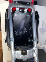
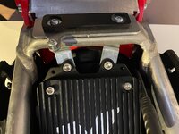
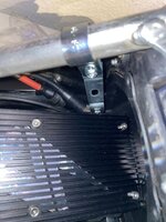
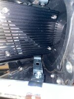
Made Fitment Brackets for the Controller inside the Airbox:
Unbenannt4.jpgUnbenannt5.jpgUnbenannt6.jpgUnbenannt7.jpg
isn´t moving a single bit now with all the force my body was able to produce.
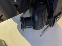
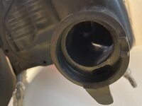
Cables will go in and out through the hole of the Carb side of the Airbox:
Unbenannt9.jpgUnbenannt10.jpg

once all the wiring is tested I will double heatshrink every connection and put liquid insulation tape around anything electronically thas exposed to the elements.
I want it to be fully capable of beeing pressure washed from any angle.


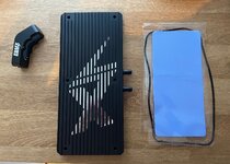
I also bought the Watercooling Heatsink for the controller:
Unbenannt8.jpg

But thats just to have it if needed I will leave the Air Heatsink on it for now and see if it ever gets so hot that it would make sense to add the watercooling since this would add additional wight for Pump, Hoses and Radiators.


Spending time now on the little things until the battery arrives
Getting it clean in every edge,
grease all bearings,
Locktite all the Screws I touched in the Build Process,
finding the perfect route for the wiring (secure and away from moving parts),
remove all those old 24MX Decals.
 

fmxxx666

Active member
Likes
40
Location
Hamburg Germany
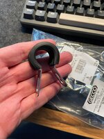
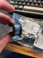
@unluckypanda haha I have no idea what these things are called xD I just ran through the local Hardware Store and looked for something that has nuts or screws attached and mounts on something round so I ended up in the Plumbing corner and found these:
Unbenannt11.jpgUnbenannt12.jpg

as I was not smart enough to measure the diameter fo the frames pipes before so I just grabbed a bunch in different sizes, test fitted at home installed the ones that where fitting the tightest and brought back the other ones :rolleyes: always two of these where connected to a Metal Plate with three holes in it, these I streched out and used them as the attachment plates to mont the Controller.


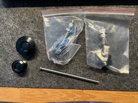
for all interested in the "Push Lock" things I just recieved them and they are awesome

Unbenannt13.jpg

Planning to mount the tank + plastics and seat with that system so I can quickly Change or take out the Battery since I guess I will never store the Battery inside the Bike when not in use so I will have often the case to take out the Battery.

the TX-Race Restyle kit has a super annoying Screw on the back of the Seat this takes me always 5 min to align and get screwed in since you need to hit a nut underneath that is invisible while you are doing it so this push lock makes it a seconds thing:
 

fmxxx666

Active member
Likes
40
Location
Hamburg Germany
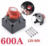
Hi @DonCox and of cause all others I am wondering is there a specific reason you and other use these type of „kill switches“ on their builds?

IMG_1964.jpeg

This was the „highest spec“ one I could find… is there a version for 72V and above?
Which variants you use?


My setup currently would be battery > QS10 connector > controller.

I would disconnect the QS10 everytime I am not riding. And most likely also take out the battery to not have to leave it in the cold garage.


so your setup is then Battery > qs10 > kill switch (with little resistor to precharge the capacitors of the controller) > controller.

Is the (only) benefit that you could disconnect the battery quick and easy without having to touch the QS10?
Or does it serve any other purpose security wise or so?
How about a breaker or a fuse?

As my battery will be open discharge as well I was wondering if I need a breaker or a fuse as currently there is nothing protecting against a short in my setup between battery and controller.
If so what spec should the breaker have?
 

DonCox

Well-known member
Likes
417
Location
Lake Havasu City, AZ
In lieu of a contactor to totally disconnect the battery from the bike, controller, system, we use this switch. I know that they are only rated up to 60V, but they have been very reliable in our application.
I agree with you about an inline fuse very early on in the wiring, Maybe on the top of the battery an ANL fuse. Those are only rated at 48-60V, yet they are on top of all controllers, Sevcon, Kelly, Votol.
We have been looking at this recently, a Marine Stud mounted fuse. Marine Rated Battery Fuses
Or something similar since we run open discharge batteries also.
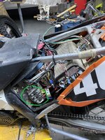
I have tested solid copper wire also ( I used it in an earlier bike build, 2mm diameter copper wire, short length, will blow at 400+ A. 1mm copper wire will blow at 90A. Here the holder I used for the wire tests. (circled in green)The bike would draw 400A, I had a current meter on it.

400A wire Fuse.jpg
 

DonCox

Well-known member
Likes
417
Location
Lake Havasu City, AZ
Hi @DonCox and of cause all others I am wondering is there a specific reason you and other use these type of „kill switches“ on their builds?

View attachment 12401

This was the „highest spec“ one I could find… is there a version for 72V and above?
Which variants you use?


My setup currently would be battery > QS10 connector > controller.

I would disconnect the QS10 everytime I am not riding. And most likely also take out the battery to not have to leave it in the cold garage.


so your setup is then Battery > qs10 > kill switch (with little resistor to precharge the capacitors of the controller) > controller.

Is the (only) benefit that you could disconnect the battery quick and easy without having to touch the QS10?
Or does it serve any other purpose security wise or so?
How about a breaker or a fuse?

As my battery will be open discharge as well I was wondering if I need a breaker or a fuse as currently there is nothing protecting against a short in my setup between battery and controller.
If so what spec should the breaker have?
Hey you made me think a little more about this. I am going to build a QS10 connector with a fuse in between the male a female connector, so it will just go in line with the battery output cable. Here is just a sketch of the idea.

IMG_7419[1].JPG
 

fmxxx666

Active member
Likes
40
Location
Hamburg Germany
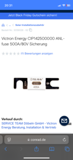
@DonCox that’s exactly how I was thinking right now. After some googling in the world of electric forklifters there are plenty ANL and CNL fuses available rated 80v dc and even up to 125v dc with 300 / 400 or 500A


IMG_1965.png
I will get one of those with a waterproof ANL fuse holder I guess
 

Dave Daum

Member
Likes
16
Location
San Diego
Hi Guys,
My E&C motor and controller kit arrived today. Thanks to everyone's tips I've been able to make some major progress. Now I have to wait patiently for the battery. Here is a video showing the status of my CRFE build:
 

Dave Daum

Member
Likes
16
Location
San Diego
Hey you made me think a little more about this. I am going to build a QS10 connector with a fuse in between the male a female connector, so it will just go in line with the battery output cable. Here is just a sketch of the idea.

View attachment 12403
Nice schematic. So, you are running the on/off switch in parallel on the B+ power cable. You are recommending a 400A fuse on B+ upstream from the switch.
Questions:

1. Just a simple break in the connection, with little to no load, is enough to cause concern?
2. The EM260 control has a 300A fuse: Is that 300A fuse not sufficient for protection?
3. Should we also install a 400A fuse in the EM260?

Please forgive my too simplistic questions.

-- Dave
 

DonCox

Well-known member
Likes
417
Location
Lake Havasu City, AZ
Nice schematic. So, you are running the on/off switch in parallel on the B+ power cable. You are recommending a 400A fuse on B+ upstream from the switch.
Questions:

1. Just a simple break in the connection, with little to no load, is enough to cause concern?
2. The EM260 control has a 300A fuse: Is that 300A fuse not sufficient for protection?
3. Should we also install a 400A fuse in the EM260?

Please forgive my too simplistic questions.

-- Dave
I don't understand the question #1. And I am running the ON/OFF switch in series with the B+ power cable and the new fuse will be in series also, before the ON/OFF switch. I would recommend a 400A fuse on the controller., I have pushed that much out of my controller, but I have never blown one, I would think a 300A would blow.
 

DonCox

Well-known member
Likes
417
Location
Lake Havasu City, AZ
Hi Guys,
My E&C motor and controller kit arrived today. Thanks to everyone's tips I've been able to make some major progress. Now I have to wait patiently for the battery. Here is a video showing the status of my CRFE build:
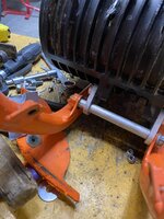
I can see that you used the universal mounts from Lithium King. ( the long slots in the front) . These motors in this application are creating a lot of torque. Are your mounts steel? I would weld the back mount to the spacer on the swing arm bolt, and weld the spacer in the front between the original mounts to the mounting plates. The motor will try to go up in the front, and the slotted holes are pretty long. We have had problems before with Mighte mounts and bolts and mounts coming loose. I prefer getting custom mounts from Lithium with exact holes for all mounts, so if you weld the spacer in the front to the mount over the slots it will make it much solider

IMG_6839.JPG

IMG_6842.JPG

IMG_6846.JPG
 

fmxxx666

Active member
Likes
40
Location
Hamburg Germany
@DonCox
@Dave Daum

as a dude with zero Welding capabilities or any deeper knowledge...
as far as I am aware welding Steel Mount to Aluminium tube is not possible right?
So I would need the spacer pipes then made from Steel?

anyway as I want my Build to be as good as possible I may also get some Custom Mounts made (and if its just for the looks that its no longer the universal one)
But while ordering at lithium King I noticed that the Custom mount @DonCox let made for the CRF450 Build the motor sits significantly higher than on my Universal Mounts:
Unbenannt3.jpgUntitled.jpg
is there a reason for it?
In a lot of DIY MX Build videos I see on YT I can hear clearly loud chain rattling when accelerating... is that maybe due to a too low QS Mount so the chain working against the Swingarm chainguide all the time?
Here is a video I found where you can hear this ratterling he is also using the Lithium King Universal Mounts:
 

bayodome

Well-known member
Likes
125
Location
Brooklyn, NY
@DonCox
@Dave Daum

as a dude with zero Welding capabilities or any deeper knowledge...
as far as I am aware welding Steel Mount to Aluminium tube is not possible right?
So I would need the spacer pipes then made from Steel?

anyway as I want my Build to be as good as possible I may also get some Custom Mounts made (and if its just for the looks that its no longer the universal one)
But while ordering at lithium King I noticed that the Custom mount @DonCox let made for the CRF450 Build the motor sits significantly higher than on my Universal Mounts:
View attachment 12538View attachment 12540
is there a reason for it?
In a lot of DIY MX Build videos I see on YT I can hear clearly loud chain rattling when accelerating... is that maybe due to a too low QS Mount so the chain working against the Swingarm chainguide all the time?
Here is a video I found where you can hear this ratterling he is also using the Lithium King Universal Mounts:
My conversion is no different. I think most of the chain rattle happens ALL the time on every MX bike. The difference is that there's no engine noise to drown out the other noises (chain, suspension, wheels, the random wire or cable slapping against plastic or the frame). Dirt bikes go through absolute torture, and we're now only just realizing how much noise they make even without an ICE.

It really makes you appreciate how much work Stark put into soundproofing the Varg.

Having ridden Electro & Co's YZ-EMX conversion, I also give that team a ton of credit for creating a very rattle-free machine. Not easily accomplished on a limited budget.
 

Dave Daum

Member
Likes
16
Location
San Diego
I can see that you used the universal mounts from Lithium King. ( the long slots in the front) . These motors in this application are creating a lot of torque. Are your mounts steel? I would weld the back mount to the spacer on the swing arm bolt, and weld the spacer in the front between the original mounts to the mounting plates. The motor will try to go up in the front, and the slotted holes are pretty long. We have had problems before with Mighte mounts and bolts and mounts coming loose. I prefer getting custom mounts from Lithium with exact holes for all mounts, so if you weld the spacer in the front to the mount over the slots it will make it much solider

View attachment 12532

View attachment 12533
I agree wholeheartedly. The Lithium-King universal stainless steel mounts seam fairly solid. Custom fitted and welded mounts will undoubtedly provide greater strength. And, they will look trick.

Everyone's input is so appreciated. I am certain there will be several improvements to make after testing at the track. Following the first ride, I'll tear the bike down and make changes. Until then, I'll do my best to avoid rework by listening to everyone. -- Dave
 

DonCox

Well-known member
Likes
417
Location
Lake Havasu City, AZ
A lot of good questions and observations. First you are correct about welding aluminum to steel, it doesn't work. But you can weld steel to Stainless. So I would weld the new brackets to the swingarm tube in the rear, and in the front I would weld a steel or stainless spacer between the new brackets.
The two picture of the different mounts, in mine the motor is rotated slightly more to the rear than yours, thus the front bolt is slightly higher. We both are close enough to the best spot, not to be a problem.
As Bayodome said, you will hear many more noises on an electric bike. On the newer KTM's they don't use rollers for the chain, but flat guides, and the chain slap is more noisy. The rollers on my Yamaha seem to be quieter. The chain type also plays into the noise. O-ring and xring chains are quieter. And I have found in all the bikes I have built (over 15) every one has a unique motor sound. Some I almost think there is a problem, but it is just unique sound. Then the tire is very noisy. The first Alta I rode had Moose's in the tires, and I thought I had a flat tire. And last is the chain tension. Make sure this is loose enough, I have destroyed a output main bearing with too much tension. Take the shock out and run the swingarm through the travel, to confirm a good spot for adjustment.
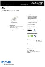
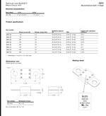
I like that new AMH fuse you found fmxxx666, thanks.
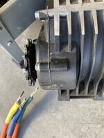
We had one bike tear up the bolts and mounts, and ruined the case of the motor in the rear. The motor was hitting the Swingarm and it wore the side of the sprocket severely. Look closely at the sprocket, and the back of the motor gear reduction.

IMG_5263.JPG
 

Dave Daum

Member
Likes
16
Location
San Diego
A lot of good questions and observations. First you are correct about welding aluminum to steel, it doesn't work. But you can weld steel to Stainless. So I would weld the new brackets to the swingarm tube in the rear, and in the front I would weld a steel or stainless spacer between the new brackets.
The two picture of the different mounts, in mine the motor is rotated slightly more to the rear than yours, thus the front bolt is slightly higher. We both are close enough to the best spot, not to be a problem.
As Bayodome said, you will hear many more noises on an electric bike. On the newer KTM's they don't use rollers for the chain, but flat guides, and the chain slap is more noisy. The rollers on my Yamaha seem to be quieter. The chain type also plays into the noise. O-ring and xring chains are quieter. And I have found in all the bikes I have built (over 15) every one has a unique motor sound. Some I almost think there is a problem, but it is just unique sound. Then the tire is very noisy. The first Alta I rode had Moose's in the tires, and I thought I had a flat tire. And last is the chain tension. Make sure this is loose enough, I have destroyed a output main bearing with too much tension. Take the shock out and run the swingarm through the travel, to confirm a good spot for adjustment.
I like that new AMH fuse you found fmxxx666, thanks.
We had one bike tear up the bolts and mounts, and ruined the case of the motor in the rear. The motor was hitting the Swingarm and it wore the side of the sprocket severely. Look closely at the sprocket, and the back of the motor gear reduction.

View attachment 12560

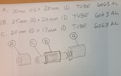
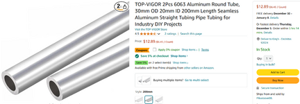
When I first started installing the motor mounts I was super concerned with the Lithium-King motor mounts sliding around on the 17mm ID x 20mm OD tube. I wanted more support. I ended up fabricating three tubes that would slip over the 20mm OD and sandwich the the motor mount plates. I had to lightly sand the 20mm OD in order for the larger tubes to slide over it. Note; I plan to replace the 25mm OD x 20mm ID tube in the center with a 30mm OD x 20mm ID tube. I'll do this next disassembly. Below is a sketch showing the arrangement:

1733269057340.png
1733269641829.png
 
Top Bottom